分布式放大器是高频微波工程中的独特电路
October 22, 2019
本博文首次由自定义MMIC发布who joined the Qorvo family2020年2月。定制MMIC以其一流的模具和包装组件而闻名,这增加了我们的功率放大器,以使多芯片模块用于广泛的防御,航空航天和商业应用。
 这distributed, or wideband, amplifier is a unique circuit in the field of high frequency microwave engineering. Its architecture can often be misunderstood, however, and this confusion can sometimes result in a non-optimal use of the amplifier. In this note, we will explain the inner workings of a distributed field effect transistor (FET) amplifier and how best to use this circuit in a microwave system.
在a traditional FET amplifier design, the active devices are individually tuned and matched with lumped or distributed networks to obtain a specific frequency response. Designers of such amplifiers must make tradeoffs relative to bandwidth, efficiency, gain and flatness such that a maximum achievable bandwidth is typically no more than one to two octaves.
When a larger bandwidth is needed, designers turn to distributed amplifiers. The concept of a distributed amplifier was first conceived by William S. Percival in 1936[1]并于1948年推广到吉扎顿,惠州,贾斯伯格和诺埃[2]。分布式放大器通过创建一对传输线来函数。一个传输线连接基于FET的放大器中的器件的输入或栅极,然后用电阻终止。其他传输线将输出或驱动器连接在基于FET的放大器中,并提供放大器的输出。分布式放大器设计器必须小心匹配输入和输出线的延迟,以确保每个晶体管和链中的其他设备同相的输出。每个单独的FET看到的实际阻抗变化,但是输入和输出均匹配在宽带宽度范围内与某些特征阻抗Z匹配0.,微波应用中通常为50欧姆。这种方法使得可以通过极宽的带宽实现性能,这些带宽主要由截止频率限制(fT.)用于开发放大器的技术,而不是利用集总元件匹配网络的放大器的一个到两个八倍的实际限制。

图1:具有Cascode配置的概念N级分布式放大器
除了这种分布式方法之外,许多基于MMIC的分布式放大器使用CASCODE配置,该级联配置包括公共源FET作为放大器的输入和由该输入级作为输出驱动的公共栅极FET。该架构提供了几个优点,包括更高的输入和输出阻抗,更高的增益和更广泛的带宽。示出了具有Cascode配置的概念N级分布式放大器图1。
了解这种架构对于了解其优缺点至关重要。与任何放大器一样,性能特性,如增益,返回损耗,噪声系数,电源,线性度和效率都非常重要,但在为应用选择分布式放大器时,有几个其他因素需要考虑。
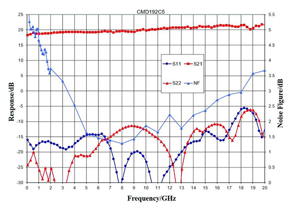
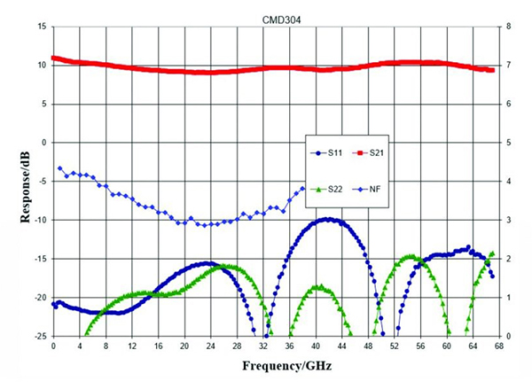
首先,传输线通常在较高频率下具有比下频率更高的损耗,主要是由于金属的肤质。在分布式放大器中也发生这种现象,这可能导致随着频率的增加而倾斜的增益。由于大多数宽带系统都需要增益跨越宽频率范围,因此具有负增益斜率的分布式放大器的选择将需要额外的组件来均衡增益,并且不必欢迎这种解决方案。然而,可以相对于频率创建平坦,甚至正增益斜率。例如,如图所示图2, 这CMD192C5分布式放大器相对于DC-20 GHz的频率具有正增益斜率。通过消除其中一些均衡阶段并降低设计实现的尺寸,功率和复杂性,这种性能对宽带系统设计者提供了相当大的优势。在甚至甚至更广泛的频带系统的情况下,在正增益斜率可能无法实现的情况下,相对于频率的平坦响应提供了类似的优点。这CMD304例如,是DC-67 GHz分布式放大器,具有相对于频率的平坦增益响应,如图所示图3.。

图2:CMD192C5分布式放大器的S参数和噪声数字与频率

图3:CMD304分布式放大器的S参数和噪声数字与频率
其次,另一个放大器的特征,如图所示图2和3.是低频噪声系数。在分布式放大器中,噪声数据不仅受到信道和栅极噪声的影响,因为它在其他放大器拓扑中,但它也受到输入端接的热噪声的影响。在达到输出之前滤出来自该终止的噪声,使得它在B / N下面只有很大的影响,其中N是放大器级的数量,B是设备的带宽[3]。回到图2,显然,由于输入终端的噪声,CMD192C5低于4GHz的噪声系数正在增加。在图3., however, the low frequency noise figure of the CMD304 is much flatter than the CMD192C5 even at 1 GHz, the lowest measured frequency point for the CMD304. The reason: the CMD304 has many more FET stages than the CMD192C5. Therefore, if low frequency noise figure is an important system consideration, choosing a distributed amplifier with more stages is a preferred solution. Additional techniques can be employed to further reduce the effect of this termination on the low-frequency noise figure and future products featuring these techniques will provide good noise performance well below the B/n limit.
Next, some wideband applications also require the amplifiers to have low additive phase noise. Such amplifiers are critical for many applications where received power levels can be very low, such as high-end direct conversion receivers or radar systems. In these wideband systems, designers must use an amplifier which does not contribute to the system phase noise, as the additive noise could potentially obscure the desired signal after mixing with the LO. However, it is well known that the additive phase noise of FET-based amplifiers can be quite high. Therefore, to achieve low-phase-noise distributed amplifiers, circuit designers turn to hetero-junction bipolar transistor (HBT) processes. HBTs are known to have very low 1/f noise, which gives amplifiers of this type extremely low additive phase noise. TheCMD275P4是极其宽带低相位噪声放大器的示例。与在PHEMT过程上设计的类似的宽带部件相比,在HBT过程上开发的该组分在10kHz偏移下显示了大约20dBc / Hz的相位噪声的改进。

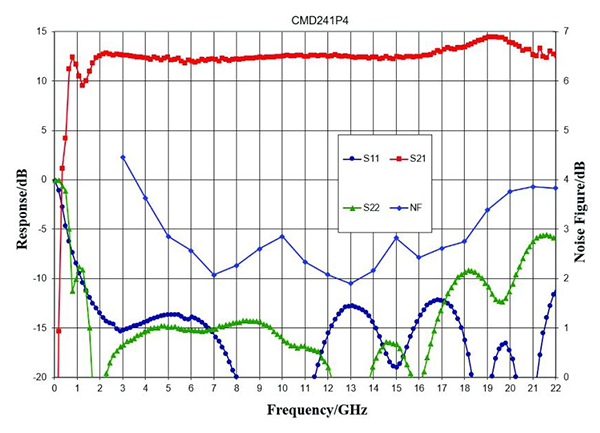
图4:S参数和噪声数字与频率CMD241P4distributed amplifier

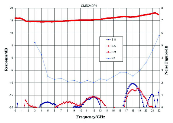
图5:S参数和噪声数字与频率CMD240P4distributed amplifier
在addition to the RF characteristics of the device, it is important to consider how the DC power will be supplied to a distributed amplifier and how the bias circuit could affect performance. In applications where size of implementation is critical and performance to very low frequencies is not necessary, most designers will select a MMIC such as the CMD241P4 with an on-chip bias choke and DC blocking capacitors on the RF input and output. While reducing the total footprint required by the amplifier, these on-chip components limit performance, not only because the DC blocking capacitors will limit the low end, but also because the higher resistance of the on-chip bias choke - when compared to a high-quality conical inductor - affects the high frequency performance as well. In order to understand the limitations,图4.和5.显示CMD241P4与片上偏置结构的性能(图4)以及CMD240P4,其特征具有与片外偏置的相同的放大器设计(图5)。
虽然小尺寸和易于实施是几乎任何系统的目标,但在某些设计中,尽可能接近实际的直流性能,而不会限制高频性能,即使在船上的空间的费用中也是至关重要的。有许多分布式放大器专为这些应用而设计,该应用需要在RF线上的片外偏置扼流圈和直流阻挡电容器。该架构允许系统设计人员通过选择将提供最广泛性的性能所需的性能。必须非常仔细地选择右外部元件以确保分布式放大器的正确性能。首先,设计人员必须选择宽带电感,可以处理具有足够余量的设备所需的偏置电流,并且其中没有任何影响性能的带内共振。还需要选择直流阻挡电容器而没有任何带内谐振,同时能够通过应用所需的最低频率。
除了典型的放大器参数之外,还有许多不同的因素考虑,宽带系统设计人员可以使用各种分布式放大器选项至关重要。自定义MMIC的越来越多的分布式放大器产品组合包括高功率,低噪声,极宽的带宽和低相位噪声选项。这些放大器中的大多数相对于频率呈现平坦或正增益斜率,并且存在片上和外部偏置的选项。这宽度的褶皱确保宽带系统设计人员始终可以选择满足越来越多的高性能的需求,跨越极宽的带宽。
参考
- W.S.Percival,“热离子阀门电路”,英国专利说明书。1937年7月24日提交的460,562,于1937年1月24日提交.2。吉扎顿,W.R.Hewlett,J.H.Jasberg,J.D.Noe,“分布放大”,IRE的常规,Vol。36,不。1948年8月8日。
- A. Kopa, A.B. Apsel, “Distributed Amplifier with Blue Noise Active Termination,” IEEE Microwave and Wireless Components Letters, vol. 18, no. 3, March 2008, 203.
有其他主题,您希望Qorvo专家涵盖吗?将您的建议发送给您的建议Qorvo博客team和it could be featured in an upcoming post. Please include your contact information in the body of the email.